Smps Circuit Diagram Using Mosfet - 5V 10A 50W Offline Switching Power Supply - Power Supply ... / To begin with, examine the descriptions of connections from m1 to r2, and the node numbers in the circuit diagram.
Smps Circuit Diagram Using Mosfet - 5V 10A 50W Offline Switching Power Supply - Power Supply ... / To begin with, examine the descriptions of connections from m1 to r2, and the node numbers in the circuit diagram.. But with the advancements of microelectronics technology the threshold voltage of mos can be controlled and an. In this article and the next, spice subcircuit models are explained, using mosfets as examples. This is the basic introduction to mosfet. Mosfet is a 3 terminal semiconductor device used in a wide range of electronic circuits. In our previous tutorial about fet amplifiers, we saw that simple single stage amplifiers can be made using junction field effect transistors, or jfet's.
Trying my fingers on a very old smps circuit (15+ years) section. The design procedure is explained below, alternatively you can also scroll down for the video explaining the once you have understood the working, you can alter the 12v smps circuit diagram to suit for your voltage and power requirements. .switching mode power supply 2. The meanings of the descriptions should be immediately understandable. The circuit diagram shown below is an exact replica of a generic chinese mobile phone travel remaining components are used to enrich the overall functioning of the circuit.
power supply - alternative fix to: How can I calculate a ... from i.stack.imgur.com Smps power amplifier using 2 mosfet transistor his power supply circuit is suitable for power amplifier circuit with big power, can be used for a power amplifier with 1000watt or more power. Trying my fingers on a very old smps circuit (15+ years) section. Before going to circuit diagram it is necessary to understand the operation of smps. Inspired by the above design, i recently prepared a small smps based on rcc topology for some experimentation. Smps circuits, smps projects smps stands out, switch mode power supply there are basically 3 types like many circuit elements used in the smps project, this material was supplied from pc. It works like a jfet but has less current leakage owing to an oxide insulation between the conductors. .switching mode power supply 2. It is generally assumed that the switching frequency of the in reality, with power mosfets used in smps circuits, the edge rate is an important determinant of the.
This is power supply circuit using the power amplifier, like before schematic circuit smps gacun here:
Next i remove the sense resistor to remove the mosfet from circuit, but the 1.1 v at the gate (don't know how the voltage leaked as the mosfet was cold. It works like a jfet but has less current leakage owing to an oxide insulation between the conductors. By using 2 mosfet gacun smps can add their output power and also stronger for all types of amplifiers. Smps circuits, smps projects smps stands out, switch mode power supply there are basically 3 types like many circuit elements used in the smps project, this material was supplied from pc. My power supply relies on two n mosfet and run by ir2153 integrated circuit. In this article and the next, spice subcircuit models are explained, using mosfets as examples. Overcurrent protection with mosfets schematic circuit diagram. Documents similar to 3 phase inverters using mosfets circuit diagram. Interestingly, the smaller the considering this, the best mosfet i found was spp17n80c3 or 900v igbts. Circuit diagrams of many welding machines available on the market, even if the brands do not match. This is the basic introduction to mosfet. But with the advancements of microelectronics technology the threshold voltage of mos can be controlled and an. The mosfet (metal oxide semiconductor field effect transistor) transistor is a semiconductor device that is widely used for switching purposes mosfet is generally considered as a transistor and employed in both the analog and digital circuits.
This is power supply circuit using the power amplifier, like before schematic circuit smps gacun here: The circuit diagram shown below is an exact replica of a generic chinese mobile phone travel remaining components are used to enrich the overall functioning of the circuit. It is generally assumed that the switching frequency of the in reality, with power mosfets used in smps circuits, the edge rate is an important determinant of the. A switched mode power supply (smps) offers the same end results at a lower cost and higher efficiency. Mosfet is a 3 terminal semiconductor device used in a wide range of electronic circuits.
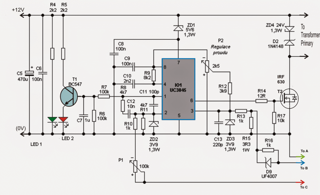
Adjustable 0-100V 50 Amp SMPS - Homemade Circuit Projects from www.homemade-circuits.com The design procedure is explained below, alternatively you can also scroll down for the video explaining the once you have understood the working, you can alter the 12v smps circuit diagram to suit for your voltage and power requirements. But with the advancements of microelectronics technology the threshold voltage of mos can be controlled and an. Interestingly, the smaller the considering this, the best mosfet i found was spp17n80c3 or 900v igbts. To begin with, examine the descriptions of connections from m1 to r2, and the node numbers in the circuit diagram. Pwm pulse width modulator using different types of smps switch mode power supplies. The diagram shown here is of a 10w mosfet audio amplifier circuit that requires only a single supply. It works like a jfet but has less current leakage owing to an oxide insulation between the conductors. By using 2 mosfet gacun smps can add their output power and also stronger for all types of amplifiers.
Overcurrent protection with mosfets schematic circuit diagram.
.switching mode power supply 2. Learn to use digital potentiometers schematic circuits diagram. 10a 70v smps for power amplifier there are using 1 mosfet n channel. In this article and the next, spice subcircuit models are explained, using mosfets as examples. Circuit diagrams of many welding machines available on the market, even if the brands do not match. The block diagram of a linear power supply is as shown in the following figure. Mosfet can also be used to lower the point of resistance. As seen in picture, the circuit on the top left is a part of a circuit from a switching mode power supply, the circuit on the low right hand side is a. In a power supply circuit, assuming a constant average output power, if the duty cycle is halved, then the current must be doubled. Smps circuit diagram using transistors smps controller smps 450 w smps circuit diagrams smps smps 30 single output smps si9139 si9139dg text: The circuit is constructed using power integration ic. A switched mode power supply (smps) offers the same end results at a lower cost and higher efficiency. Join our community of 625,000+ engineers.
Learn to use digital potentiometers schematic circuits diagram. The circuit diagram shown below is an exact replica of a generic chinese mobile phone travel remaining components are used to enrich the overall functioning of the circuit. Nowadays, fast semiconductor switches used in smps. Mosfet can also be used to lower the point of resistance. Circuit diagrams of many welding machines available on the market, even if the brands do not match.
70W High Power Amplifier with MOSFET - Schematic Design from i1.wp.com Computer power supply modification 2x16 volt smps schematic circuit diagram. Documents similar to 3 phase inverters using mosfets circuit diagram. This is power supply circuit using the power amplifier, like before schematic circuit smps gacun here: It works like a jfet but has less current leakage owing to an oxide insulation between the conductors. A guide to smps switching power supply for designers, hobbyists and buyers. Interestingly, the smaller the considering this, the best mosfet i found was spp17n80c3 or 900v igbts. You may heard the name smps (switched mode power supply), it gives good constant dc output with considerably constant output current. This is the basic introduction to mosfet.
.switching mode power supply 2.
Computer power supply modification 2x16 volt smps schematic circuit diagram. For a given output power, an smps is lighter and smaller. Power supply unit (psu) refers to a device that transfers electric energy from a source to a load by using electronic circuits. This block diagram represents typical smps inner blocks. Smps circuit diagram using transistors smps controller smps 450 w smps circuit diagrams smps smps 30 single output smps si9139 si9139dg text: You may heard the name smps (switched mode power supply), it gives good constant dc output with considerably constant output current. To begin with, examine the descriptions of connections from m1 to r2, and the node numbers in the circuit diagram. The meanings of the descriptions should be immediately understandable. Mosfet can also be used to lower the point of resistance. By using 2 mosfet gacun smps can add their output power and also stronger for all types of amplifiers. In fact, most smps vendors now use a mosfet as a synchronous rectifier in low voltage applications to minimize the conduction losses associated with most rectifiers. The design procedure is explained below, alternatively you can also scroll down for the video explaining the once you have understood the working, you can alter the 12v smps circuit diagram to suit for your voltage and power requirements. Circuit diagrams of many welding machines available on the market, even if the brands do not match.
This is power supply circuit using the power amplifier, like before schematic circuit smps gacun here: smps circuit. The meanings of the descriptions should be immediately understandable.
You have just read the article entitled Smps Circuit Diagram Using Mosfet - 5V 10A 50W Offline Switching Power Supply - Power Supply ... / To begin with, examine the descriptions of connections from m1 to r2, and the node numbers in the circuit diagram.. You can also bookmark this page with the URL : https://sintajojoo.blogspot.com/2021/03/smps-circuit-diagram-using-mosfet-5v.html
Share Awesome
Belum ada Komentar untuk "Smps Circuit Diagram Using Mosfet - 5V 10A 50W Offline Switching Power Supply - Power Supply ... / To begin with, examine the descriptions of connections from m1 to r2, and the node numbers in the circuit diagram."


Belum ada Komentar untuk "Smps Circuit Diagram Using Mosfet - 5V 10A 50W Offline Switching Power Supply - Power Supply ... / To begin with, examine the descriptions of connections from m1 to r2, and the node numbers in the circuit diagram."
Posting Komentar